Mechanical

Flanged bushing: bolt the flange down, run the shaft through

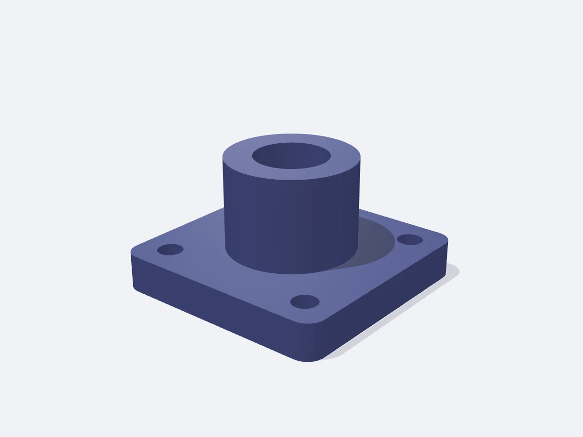
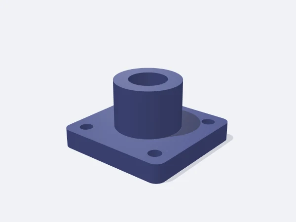
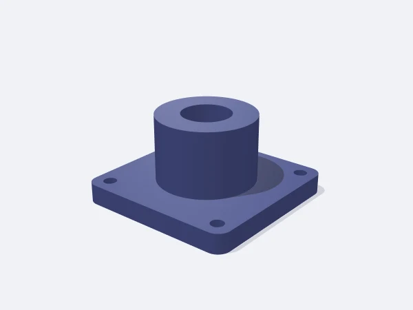
This page opens the DrawSTL flanged bushing template: a parametric bearing bushing with a square flange that screws to a surface while a shaft or tube passes through its boss, sized in millimetres and downloaded as a print-ready STL. The flange carries a screw hole at each corner, and you set how far out that pattern sits as a percentage.

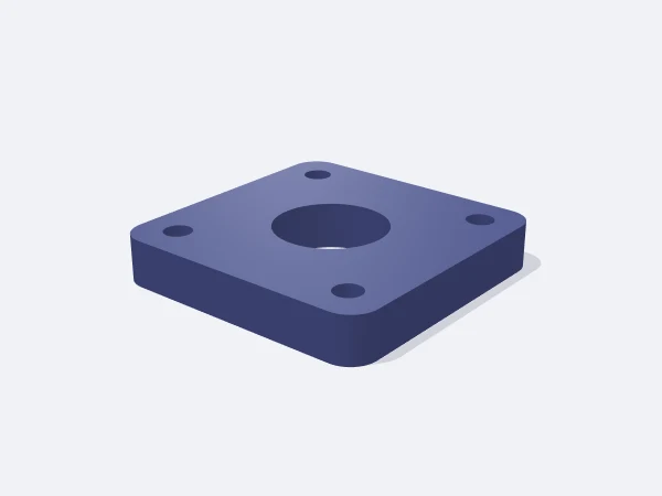
The boss is the cylinder rising above the flange, and the bore runs through both. A longer boss means longer shaft engagement. Set the boss length to zero and no boss is built, leaving a plain drilled flange plate.

Free, no sign-up. Change the sizes in millimetres and download the STL.

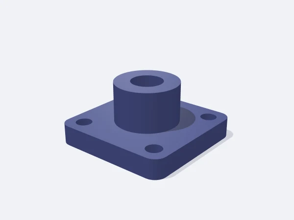
DrawSTL flanged bushing template: a square flange with a cylindrical boss in the middle, a through bore and screw holes at the four corners

Ready-made variants

Each variant is the same template with different settings. Follow the link and the editor opens with those values.

Adjustable sizes

These values are edited in the editor's template panel. A number outside the range is clamped to the nearest limit automatically.

SizeRangeDefault
Dimensions
Flange side20–140 mm50 mm
Flange thickness2–25 mm8 mm
Corner radius0–25 mm4 mm
Body
Boss diameter6–100 mm28 mm
Boss height0–80 mm20 mm
Bore2–80 mm16 mm
Mounting
Screw hole0–14 mm5.5 mm
Hole spacing (%)40–9272

What it is used for

  • Supporting the end of a shaft, lead screw or linear rail on a panel
  • A pass-through sleeve for pipe or a cable bundle in an enclosure wall
  • The pivot bearing for a lever, pedal or hinged lid
  • A shaft anchor point in CNC and 3D printer builds
  • The fixed half of a fan, pulley or wheel axle

Printing tips

Orientation
The flange lies flat on the bed with the boss pointing up and the bore vertical. No rotation needed.
Layer height
0.2 mm. Drop to 0.16 mm when bore accuracy matters more than speed.
Infill
60% and up where load is involved. Four walls strengthen the material around the boss more effectively than infill.
Supports
None. The boss is a vertical cylinder, the flange is flat and the screw holes are vertical.
Material
For a turning shaft, POM or nylon gives the best sliding surface. PETG works for static support and ASA suits hot environments.

Tips

  • Make the bore 0.2-0.3 mm over the shaft size for rotation, or 0.05-0.1 mm over for a press fit.
  • If the corner holes would come closer than 0.8 mm to the edge or the boss, the template skips them; reduce the diameter or the spacing.
  • Keep the boss at least half the bore diameter long, otherwise the shaft rocks in the bearing.

Bore, boss and shaft engagement

How well a bearing holds a shaft comes down to the ratio of engagement length to bore diameter. A shaft passing through a short hole tilts under the smallest side load, while a longer hole keeps it on axis. That is what the boss does: it extends the guided length beyond the flange.

As a working rule, flange thickness plus boss length should be at least half the bore diameter, and the boss should stay 1.5 to 2 mm above the bore so material remains around it.

  • Bore + 0.05-0.1 mm: press fit, the shaft will not turn
  • Bore + 0.2-0.3 mm: plain bearing for a turning shaft
  • Boss length at half the bore: minimum guidance
  • Boss length equal to the bore or more: resists side loading
Screw holes and hole spacing

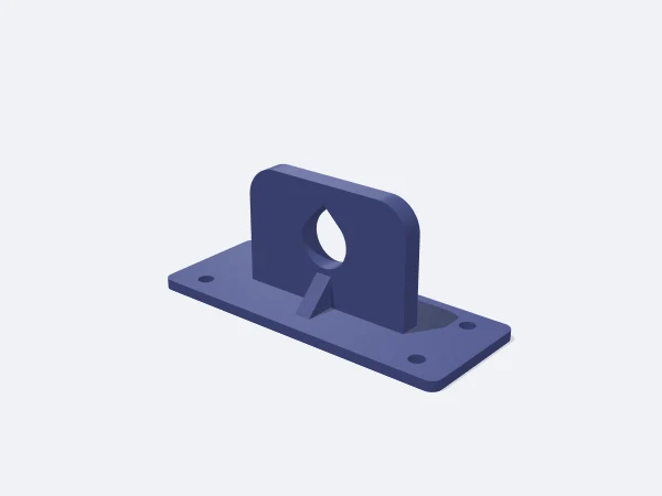
The hole spacing value sets how far out the corner holes sit, as a percentage of half the flange size. A higher percentage pushes the holes towards the corners so the screws spread load wider, while a lower one brings them closer to the boss.

The template enforces a 0.8 mm minimum wall in both directions. If the holes would come closer than that to the flange edge or the boss, no holes are cut and the panel says so. Reduce the hole diameter, reduce the spacing, or enlarge the flange.

Frequently asked questions

How much larger than the shaft should the bore be?

0.2-0.3 mm over for a rotating shaft, 0.05-0.1 mm over for a press fit. Cleaning the bore after printing helps a rotating fit noticeably.

Why were no screw holes cut?

Holes that come closer than 0.8 mm to the flange edge or the boss are unsafe and get skipped. Reduce the hole diameter or spacing, or enlarge the flange.

What happens if I set the boss length to zero?

No boss is built and you get a plain plate with the bore straight through the flange, which suits a panel pass-through or cable sleeve.

Is a printed plain bearing good enough for a rotating shaft?

At low speed and light load, yes, especially in POM or nylon. For high speed or continuous load, design a pocket for a ball bearing instead.

Can the flange be round?

This template uses a square flange bolted at the corners. For a round flange with a bolt circle, use the pipe flange template.

Similar templates

Set the sizes to fit your part

Open the template in the editor, enter your values and download a print-ready STL. No account needed.

Open in editor