Mechanical

Shaft support: set the axis height, print the bore support free

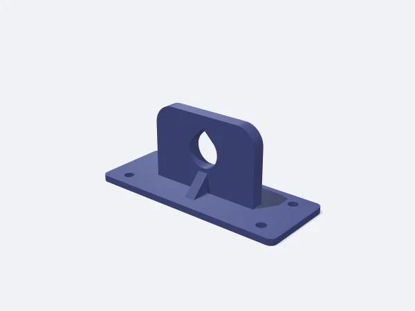
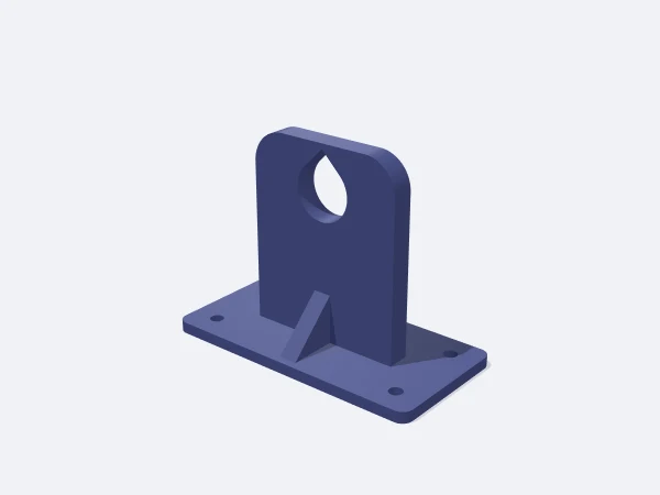
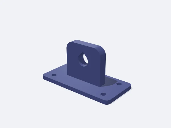
This page opens the DrawSTL shaft support template: a parametric bearing block that screws down through its base while a shaft passes through its upright body, sized in millimetres and downloaded as a print-ready STL. You set the bore and the height of the shaft axis above the bed, and the body height, wall and arched top follow from that.

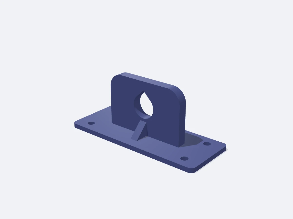
The top of the bore is built as a 45 degree teardrop, so even a horizontal hole prints without supports. The 45 degree ribs on both sides reduce how much the block flexes under side load, and base screw holes are placed automatically to clear both body and ribs.

Free, no sign-up. Change the sizes in millimetres and download the STL.

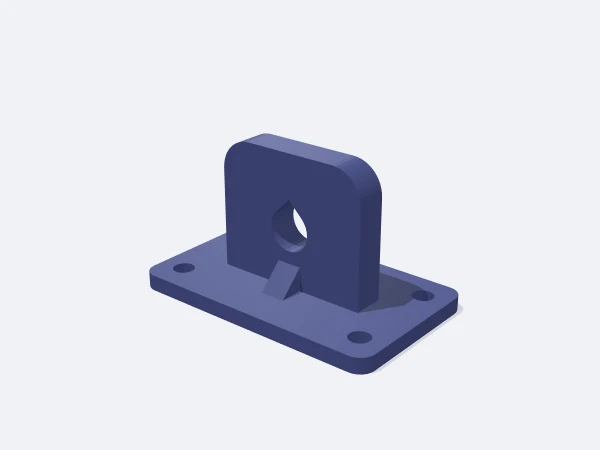
DrawSTL shaft support template: a flat screw-down base, an upright body with an arched top, a horizontal bore and 45 degree ribs on both sides

Ready-made variants

Each variant is the same template with different settings. Follow the link and the editor opens with those values.

Adjustable sizes

These values are edited in the editor's template panel. A number outside the range is clamped to the nearest limit automatically.

SizeRangeDefault
Dimensions
Base width20–160 mm124 mm
Base depth15–120 mm49 mm
Base thickness2–25 mm4 mm
Corner radius0–25 mm4 mm
Body
Body width12–120 mm70 mm
Body height15–140 mm50 mm
Body thickness4–60 mm8 mm
Shaft diameter3–80 mm20 mm
Shaft axis height8–120 mm28.5 mm
Wall around shaft2–25 mm2 mm
Rib length0–60 mm60 mm
Mounting
Screw hole0–14 mm6 mm

What it is used for

  • End support for linear rails, lead screws and plain shafts
  • Axis mounting in CNC, laser and 3D printer builds
  • Homemade winding and rotary table mechanisms
  • Anchoring lever, drum and pulley axles to a bench
  • The rotation axis for tape, roll and filament spools

Printing tips

Orientation
The base prints on the bed with the body pointing up. The bore stays horizontal, and its 45 degree teardrop top means no supports are needed.
Layer height
0.2 mm. Use 0.16 mm when bore accuracy matters more than speed.
Infill
60% and up for load-bearing supports, solid in critical spots. Keep at least 4 walls.
Supports
None. The teardrop bore, the arched top and the 45 degree ribs are all built to print support free.
Material
PETG is tougher than PLA under shaft load and vibration. Use ASA for heat exposure, and fit a separate nylon bushing inside the bore for a real sliding surface.

Tips

  • For a rotating shaft, make the bore 0.3 mm over size; the teardrop flattens the top so the shaft contacts on the sides.
  • For a static shaft, 0.1 mm over is enough, and you can add a side hole in the editor for a clamping screw.
  • Use wide washers when tightening the base screws so they do not crush the plastic.

Axis height, body height and wall

Axis height is the distance from the mounting surface to the shaft centre, and it is the defining dimension because everything else in the assembly aligns to it. Body height includes the material above the shaft, so it is always larger than the axis height.

The template checks that relation and raises the body automatically when your value leaves too little material above the bore. A 2 mm wall around the shaft is fine for light loads, while 4 to 6 mm makes a clear difference under real load.

  • Axis height: the master dimension that sets assembly alignment
  • Body height: must leave material above the bore
  • 2 mm wall around the shaft for light loads, 4-6 mm for load-bearing
  • Rib length: matters more as the axis height grows
Ribs and base hole placement

A shaft mostly pushes sideways and downwards. The upright body handles downward load easily, but side load tries to bend it fore and aft at the joint with the base, and the 45 degree triangular ribs work against exactly that.

Base screw holes are positioned by searching for a spot that clears the body and the ribs while staying inside the base edge. If no position satisfies all of that, no holes are cut; widening the base, shortening the ribs or reducing the hole diameter fixes it.

Frequently asked questions

The bore is horizontal, does it really print without supports?

It does. The top of the bore is built as a 45 degree teardrop, so there is nothing to bridge and the hole comes out clean.

Why did my body height change?

If too little material would remain above the bore, the body is raised automatically. The panel shows the new value it used.

Why were no base holes cut?

No position was found that clears the body, the ribs and the base edge at once. Enlarge the base, shorten the ribs or reduce the hole diameter.

Can I fit a ball bearing in the bore?

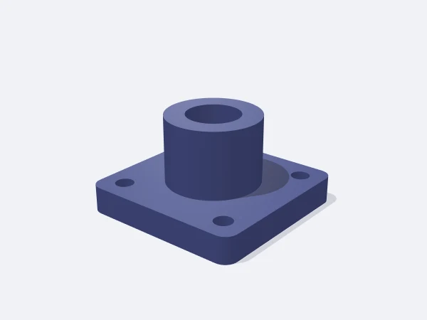
The bore is a plain cylinder with no bearing seat step. Enter the bearing outer diameter as the bore and adjust the seat depth in the editor.

How do I align two supports?

Print two copies with the same axis height and screw both to the same surface. Since axis height is measured from the mounting face, alignment follows directly.

Similar templates

Set the sizes to fit your part

Open the template in the editor, enter your values and download a print-ready STL. No account needed.

Open in editor